Check out our White Paper Series!
A complete library of helpful advice and survival guides for every aspect of system monitoring and control.
1-800-693-0351
Have a specific question? Ask our team of expert engineers and get a specific answer!
Sign up for the next DPS Factory Training!
Whether you're new to our equipment or you've used it for years, DPS factory training is the best way to get more from your monitoring.
Reserve Your Seat Today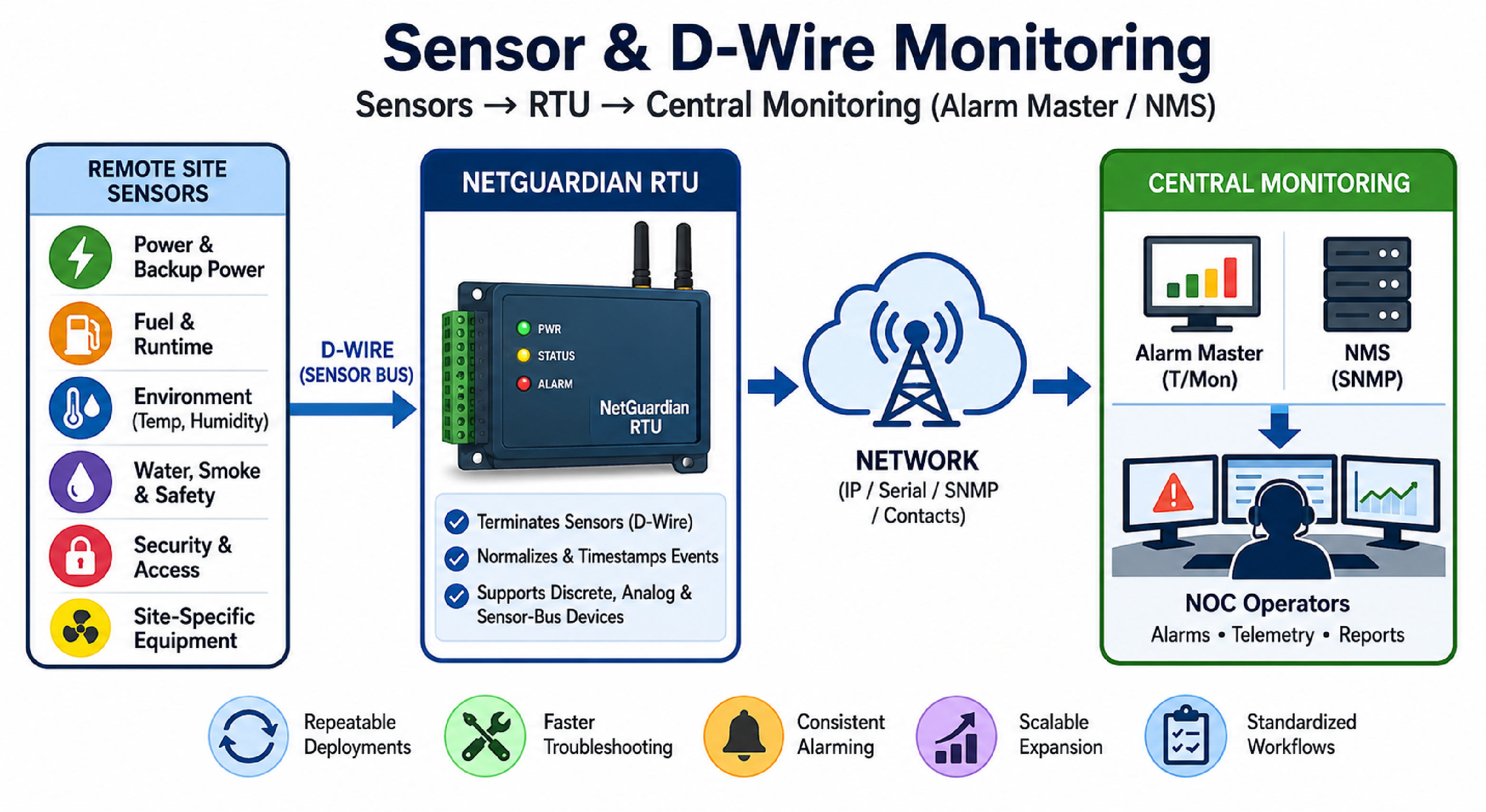
Infrastructure monitoring using sensors involves connecting physical condition sensors (power, environment, fuel, and safety) to a remote telemetry unit (RTU) so alarms and readings can be transported to a centralized monitoring system. The goal is consistent, actionable visibility into many unmanned or lightly staffed sites without building a one-off design for each location.
Organizations such as government agencies, utilities, and telecommunications operators can use a catalog-style approach to select proven sensor options first, then refine each site into a final bill of materials. The approach reduces engineering churn while preserving flexibility for different site layouts, risks, and budgets.
D-Wire monitoring is a method of interfacing sensors to an RTU using a standardized sensor bus and compatible sensor ecosystem. In practical terms, D-Wire lets a monitoring team connect multiple sensors and interfaces to a single RTU in a repeatable way, using known wiring conventions, device types, and alarm/telemetry behaviors.
D-Wire style sensor ecosystems are used when a program needs to scale across dozens or hundreds of sites and still maintain consistent documentation, spares, training, and troubleshooting procedures. A consistent sensor interface also makes it easier to normalize alarms and readings in an alarm master or NMS.
Remote site condition monitoring means measuring the non-IT signals that determine whether infrastructure stays online and safe. While each organization has different risk drivers, most monitoring programs converge on a common set of condition categories because those categories are directly tied to outages, safety events, and dispatch costs.
A common best practice is to define a standard baseline sensor kit for every site, then add site-specific sensors only where the risk justifies them. This prevents overbuilding while still giving the monitoring team consistent core coverage.
An RTU is the edge device that terminates sensor wiring and converts those signals into monitoring data. A NetGuardian RTU from DPS Telecom is commonly used for remote site visibility because it can collect discrete alarms, analog readings, and sensor-bus data, then forward events upstream using standard protocols and NOC-friendly workflows.
A typical integration pattern is: sensors connect to the RTU, the RTU normalizes and timestamps the event, and then the event is delivered to a centralized platform. Depending on the environment, delivery can be done through network protocols, serial protocols, or contact-closure outputs to an alarm master. In networks that use SNMP, some NetGuardian models can also receive and act on SNMP traps, which supports alarm integration in mixed-vendor environments.
Sensor integration choices usually fall into three signal types, and each type drives different wiring, configuration, and alarming behavior. Understanding the difference reduces misquotes and prevents commissioning surprises.
The right mix is driven by what each onsite device exposes. For example, a legacy HVAC unit may only provide relay contacts, while an environmental probe provides a calibrated measurement. A scalable monitoring program accounts for both.
A catalog-style sensor list is a practical starting point when an organization is planning a multi-site rollout. A catalog approach means selecting commonly deployed sensor and interface options first, then tailoring per site during the final engineering step. This is often the fastest way to estimate budget without pretending every detail is already known.
This approach supports budgetary planning while still giving the field team enough structure to install consistently. It also allows engineering effort to be focused on the sites that actually require nonstandard designs.
A deployment pattern is a repeatable architecture for how sensors are selected, installed, and monitored across a fleet. In remote operations, standard patterns reduce training requirements and shorten mean time to repair because every site behaves similarly in the NOC.
In many programs, the baseline is set to cover the top outage drivers: power, temperature, intrusion, and water. Fuel and generator runtime monitoring are added where backup power is part of the operational plan.
Alarm management is the discipline of presenting, prioritizing, and escalating events so operators can act quickly and consistently. An alarm master is the system that consolidates alarms from many devices, applies routing and escalation rules, and provides a single operational view.
In DPS Telecom deployments, a common architecture is to use T/Mon as the alarm master that receives events from RTUs and other network elements, then presents them to operators with consistent labeling and severity. This structure is especially useful when there is a mix of legacy contacts, SNMP sources, and multi-vendor equipment that would otherwise require multiple monitoring tools.
A sensor selection checklist is a set of requirements that ensures the deployed sensors can be installed, maintained, and alarmed in a predictable way. The checklist also protects the program from hidden complexity such as unusual power requirements or incompatible signal types.
Teams that standardize these items early typically see fewer commissioning delays and fewer confusing alarms in the NOC.
Mapping sensor categories to RTU inputs means translating real-world conditions into discrete and analog points, alarm thresholds, and notification behavior. This mapping step is where many monitoring programs either become consistent across sites or drift into one-off implementations.
| Monitoring category | Common field signal types | Typical alarm/telemetry behavior | Design considerations for multi-site programs |
|---|---|---|---|
| Power and backup power status | Discrete contacts; sometimes analog voltage | Immediate alarm on loss of utility or transfer to generator; optional delay timers | Standardize which power states are required at every site to avoid inconsistent dispatch criteria |
| Fuel and runtime indications | Analog level; discrete low-fuel contact; runtime pulse/contact | Threshold alarms (low fuel) plus trending/telemetry where supported | Document tank geometry assumptions and calibration method to avoid misleading readings |
| Environment (temperature/humidity) | Analog or sensor-bus probe | High/low threshold alarms; optional rate-of-change monitoring | Choose consistent probe placement rules (rack vs. room vs. cabinet) so thresholds remain meaningful |
| Water, smoke, and safety contacts | Discrete contacts (direct or via relay) | Usually immediate Critical alarms; often requires confirmation procedures | Define testing procedures and contact supervision approach where appropriate |
| Security and access points | Discrete door contacts; tamper switches | Door open, door forced, or door held alarms with time thresholds | Agree on operational policy for after-hours access to reduce nuisance alarms |
Remote site sensor projects fail when the physical layer and the operational layer are designed separately. The physical layer is wiring, power, and sensor placement. The operational layer is alarm naming, thresholds, and escalation. Both must be standardized for the monitoring program to scale.
A sensor bus approach standardizes how multiple sensors connect and report data, which can reduce wiring complexity and improve consistency. Dry contacts are simple and effective when a device offers relay outputs, but they do not provide richer measurements like calibrated temperature or level readings.
Start with the conditions that cause the most frequent outages or dispatches: power state, temperature, door/access, and water. Add fuel, smoke, and specialized safety inputs based on site criticality and the presence of backup power systems.
No. Many organizations start with a catalog-style list of commonly deployed sensors and interfaces to establish budget and compare options. The detailed wiring drawings can be created later for the specific sites included in the first deployment wave.
A NetGuardian RTU collects local sensor and equipment signals and forwards them to centralized monitoring using common integration methods. In SNMP environments, certain NetGuardian models can also receive and act on SNMP traps, which helps integrate mixed-vendor alarm sources.
An alarm master is designed for operational alarm handling, including consistent presentation, routing, and escalation. Many teams use an alarm master to reduce tool sprawl and to normalize alarms from RTUs, legacy contacts, and network elements that would otherwise be monitored in separate systems.
Define who owns configuration templates, who performs commissioning tests, and what the replacement process is for failed sensors. DPS Telecom also supports deployments with 24/7 technical support and a 30-Day No-Risk Money-Back Guarantee for eligible purchases, which can reduce adoption risk when standardizing new monitoring hardware.
If you are planning to expand remote site visibility using sensors, D-Wire interfaces, and an RTU-based architecture, DPS Telecom can help you convert a budgetary sensor menu into a standardized rollout plan with repeatable templates and NOC-ready alarm definitions. We can also recommend the right combination of NetGuardian RTUs, sensor options, and alarm master workflows for your environment.

Andrew Erickson
Andrew Erickson is an Application Engineer at DPS Telecom, a manufacturer of semi-custom remote alarm monitoring systems based in Fresno, California. Andrew brings more than 19 years of experience building site monitoring solutions, developing intuitive user interfaces and documentation, and opt...