Download our free SCADA tutorial.
An introduction to SCADA from your own perspective.
1-800-693-0351
Have a specific question? Ask our team of expert engineers and get a specific answer!
Sign up for the next DPS Factory Training!

Whether you're new to our equipment or you've used it for years, DPS factory training is the best way to get more from your monitoring.
Reserve Your Seat TodayModbus is an open-source protocol, which led to the widespread deployment of Modbus monitoring software systems that are most frequently used for industrial applications. It is a request-response protocol implemented using a master-slave relationship. In this relationship, communication always occurs in pairs-one device must initiate a request and then wait for a response. The initiating device, known as the master, is responsible for initiating every interaction. Typically, the master is a human machine interface (HMI) or Supervisory Control and Data Acquisition (SCADA) system. The slave is often a sensor, programmable logic controller (PLC), or Remote Telemetry Units (RTUs).
The Modbus protocol, originally designed for serial communication, has evolved significantly over the years. It is now composed of distinct layers that allow seamless integration with various network technologies. The primary layers are the Protocol Data Unit (PDU) and the Application Data Unit (ADU). Each of these serves a specific function and comes with its own set of characteristics.
Protocol Data Unit (PDU)
At the heart of Modbus is the Protocol Data Unit, which forms the core of its application protocol specification. The PDU is the structure that manages the main functionalities of the Modbus communication. Here's what it entails:
Application Data Unit (ADU)
The Application Data Unit extends the PDU by encompassing the entire data set necessary for network communication. It adapts the Modbus protocol for use with various network protocols:
Function codes in Modbus are integral to defining the actions that devices should take when exchanging data. Each code specifies a distinct task, guiding the device to validate inputs, execute commands, or manage data responses. Whether reading data or writing it, function codes ensure that both master and slave devices operate cohesively.
Importance of Function Codes
Standardized Actions: Each function code aligns with specific actions. This ensures devices can consistently interpret and execute tasks across various implementations.
Error Handling: By returning exceptions when errors occur, function codes help swiftly identify issues, such as invalid requests or unsupported actions.
How Function Codes Operate
Validation and Execution: When a device receives a request, it first checks the legitimacy of the function code, data address, and range. Successful validation triggers the relevant task execution and a corresponding response.
PDU Structure: Within a Protocol Data Unit (PDU), the function code precedes the data, dictating how the device should process this information.
Device Constraints and Data Transfer
The PDU's 253-byte cap places a limit on data size, which influences how function codes manage readings or writings. Depending on specific codes, data transfers generally range between 240 to 250 bytes.
Function Code Classes
Exceptions in Modbus
Exceptions are key to Modbus fault-tolerance. When issues arise, exceptions are communicated by modifying the function code with an exception bit. This provides quick feedback on issues without interrupting the entire communication stream. Common exception codes highlight problems such as unsupported functions or address errors, ensuring that operations remain robust.
Multiple Remote Telemetry Units (RTUs) and/or Intelligent Electronic Devices (IEDs) that support this protocol can be connected to the same physical network. This creates a Modbus network-a network of master and slave devices that communicate using the Modbus protocol. These networks typically utilize a serial connection, while Modbus TCP/IP networks will usually use 10BaseT or faster for their connection.
A common Modbus network consists of having a single master and multiple slave RTUs and/or IEDs.
The master/slave address design enables a master to communicate with a specific device by using its unique Modbus data address. This unique identifier, the address, has a range of 1 to 247. And it can be located at the beginning of the message that will be sent to the master.
A simple Modbus network can have up to 247 connected at one time the same network. Each of the 247 connected devices is assigned their own unique identifier which they will use to communicate with other devices.
Note that TCP/IP networks can generally support more devices than a traditional serial line.
In a master and slave configuration, the communication stream is controlled by the Modbus master. The master can request data from or write data to slave devices across the network using a specific register number and/or coil addresses. The Modbus slaves on the other-hand can only respond to the master's requests or commands as it is received.
The Modbus protocol has evolved into several different variations. These variations are designed to support network communications over a variety of physical network layers. These variations include Modbus RS232 and Modbus RS485, which will support different types of serial connections.
There is another variation of the Modbus protocol is called TCP/IP.
The TCP/IP specification was created in response to the expanding usage of Ethernet. Since TCP/IP is the transport protocol of the Internet, the Modbus TCP/IP specification is simply the Modbus wrapped with TCP/IP. And it can be used to communicate over a Modbus network structured with an IP connection.
Modbus internet provides a huge set of capabilities because of its compatibility with other TCP/IP support devices and software.
For example, a Modbus TCP/IP device that is located in a remote location can be still accessed through the Internet because of TCP/IP.
Two additional variants of this protocol are Modbus ASCII and Modbus RTU. These variations are optimized for use with ASCII protocol equipment and with Modbus capable RTUs. Each of the aforementioned variants uses a slightly different communication format. This allows users to deploy a Modbus network in the variant that is the most compatible with their other equipment.
A Modbus monitor advanced network should be developed using the most advanced monitoring technology. With an advanced monitoring system, you can provide automatic page and email notifications of all your alarms. With location and repair information sent directly to your technicians, you can handle network problems more quickly and efficiently.
The most advanced systems will also allow you to bring in alarms from other protocols. And they can display all of your important notifications in a single window that can be monitored by a single network operator.
A master system such as the T/Mon LNX can be what you need for your network. It is a multifunction and multiprotocol system that provides a multitude of features all in a single platform.
Modbus, SNMP, and ASCII are just a few of the many protocols supported by the T/Mon LNX. The T/Mon LNX comes with T/Mon GFX which is a graphical user interface for displaying alarms visually on a layered geographical map. Built to be the solution for a wide range of problems, it could be exactly what you need.
A communication protocol developed in 1979 by Modicon for use with their Programmable Logic Controller (PLC). It is a free and open protocol that helped get the protocol adopted by many users and devices.
A serial connection, or serial communication, is the process of sending data one bit at a time over a connection or communication channel in a sequence.
10BaseT is a twisted-pair cable that is used for LAN and can achieve speeds of up 10Mbps.
A Remote Telemetry Unit (RTU) is a device created for monitoring and reporting events that occurs at a remote site. The typical events that will be monitored are temperature, humidity, and voltage levels. Almost anything can be monitored with an RTU. Information regarding these events are collected by the RTU and then sent out to a master station like the T/Mon.
An Intelligent Electronic Device (IED) is a microprocessor-based controller that has advanced local control intelligence.
TCP/IP is used as the transport protocol of the Internet and is made up of two different protocol layers. The first layer, the transport layer, is also called the Transmission Control Protocol (TCP). It is used to break up a message or file into smaller pieces of data called packets, then send them over the Internet.
It is also responsible for rearranging the packets when it receives them. The second layer is the Internet layer. It is called the Internet Protocol (IP) and it is used for addressing the packets so that the packets will get to the correct destination.
If you work in telecom, you probably have trouble with any remote RS485 Modbus equipment. The world has shifted more and more to IP, T1, fiber, and other modern transport standards. Dedicated serial lines are tough (and expensive) to maintain. Wouldn't it be nice to route serial traffic over IP? Then you could keep you old-but-still-functional Modbus gear but abandon the aging serial transport.
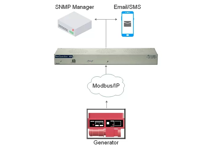
One excellent new solution to this problem is a remote Modbus-to-SNMP mediator. This is a fairly simple box that takes in serial Modbus (RS-232 or RS-485) and converts the Modbus message to standard SNMP traps. These can be received by your SNMP manager. Because the mediator box is modern, you benefit from recent innovations like SNMPv3.

Unlike earlier versions of SNMP, SNMPv3 is secured with encryption. For many organizations, this level of security is needed whenever data will be sent via IP.
If serial transport isn't your problem, but you still want to integrate Modbus into your SNMP umbrella, you can take a different route. This involves using a Modbus mediating master station to convert inbound Modbus to SNMP. This single stream of usable SNMP traps can be easily sent to your preferred SNMP manager. This master-station solution will generally be much less expensive than installing individual mediation devices at each of your remote sites.
If you work with any kind of legacy equipment, including serial Modbus, you need very specialized gear to make it work in today's networks. That's where your choice of manufacturer comes in. Some just sell commodities, if you need a very unique solution, you're out of luck.
What you need to get a custom solution is a manufacturer who can take a proven design and adjust the design to fit your needs. Look for a company that does its own engineering and manufacturing. They need in-house teams in those areas to be responsive to your special requests. Otherwise, they'll have a really hard time meeting your specs without an insane minimum order.
A company that farms out everything except for their "core competency" simply can't react with the speed that an integrated company can. You need a manufacturer whose core competency is being flexible and giving you the exact solution you need.
All DPS Telecom products include comprehensive technical support. If you've purchased one of our products and are encountering any kind of issue, contact DPS Tech Support today at 559-454-1600.
At DPS Telecom, the representative who answers your call isn't an intern reading from a script. DPS Tech Support representatives are engineers who contribute to product development. And, if your problem requires additional expertise, the DPS Engineering Department that designed your product is right down the hall.
Help us connect you to the right engineer by filling out this quick questionnaire. Simply leave your contact information to get started, and we'll call you back. Most preliminary discussions are about 15 minutes, and afterward, we'll send you a custom application diagram of a recommended solution that'll make it easier to justify your project to management.